|
|
请使用QQ关联注册PLM之家,学习更多关于内容,更多精彩原创视频供你学习!
您需要 登录 才可以下载或查看,没有账号?注册
x
Creating a Mill User Defined Tool! t# L' l3 S# r, d5 a0 `" y
; x6 e& A' V9 r0 k2 a8 Y
In this article we will go throUGh the stepsneeded to create a Mill User Definedtool. The purpose of this exercise is toexplain how the parameters are set when creating several different types ofcutter segments in order to gain a better understanding of how this type oftool is created. It is not the intent ofthe article to include all possible ways to create the segments.# J8 l; g v; d5 g
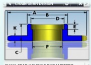
# b U7 z+ b$ s( i. K1.Set the Work Coordinate System (WCS) to the Absolute Coordinate System (ACS). Create a SkeTCh of the toolprofile on the ZX plane with thetool tip center at the X0Z0 origin and the tool axis along the Z+ axis. Positioning the Sketch in this way will allow the tool to be compared to the Sketch as the tool is created. This Sketchwill be used to determine the values used to define the tool.
% ?$ B& A5 f3 h/ s" x6 v/ ma+ T* G5 d U* K
 . g" Y* f6 Z+ a+ |. z' L4 m6 r
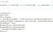
2.Create a new Mill User Defined tool and delete allbut the first segment. The first segmentwill be a line in this example. Enterthe length of the line as the “(LL) LineLength” entry and the angle as the “(LA)Line/Arc Start Angle”. In this casethe LA entry is 0 because it is inthe same direction as the X+ axis. Line entries are always created as a lengthand as an angle from the X+ axis. All other fields are set to 0. 0 L) h/ Z& k9 N5 P) c
Notice that the “(FL) Flute length” is set to 0. If this value is greater than the tool heightthe tool will not be displayed. This isespecially true while the tool is being created. The FLheight can be entered as one of the last steps in the process.0 _7 x* b! R: C8 o* k
 " M4 W! n) u6 p* R! x+ r# t( N
. m' G. R5 ^- v3.Press the “Add New Set” button to create the second Segment. This segment will define an arc. All arcs require three entries; the “(LA) Line/Arc Start Angle”, the “(AR) Arc Radius” and the “(AS) Arc Sweep”. The “(LL)Line Length” will be set to 0. The LA angle is measured from the X+ axis to a line created through thestart point of the arc tangent to the arc. The AS angle is measured fromtwo lines created from the center of the arc to the arc start and ending points. ' Y: ?/ n' E$ o6 E3 B2 @
 + J4 y8 \4 _7 V" g0 ]) ?+ d
m& [( i( R% ^4 U3 U2 ]4.Press the “Add New Set” button to create the next segment. The next two entries are a line followed by atangent arc. Because the line is tangentto the arc it is possible to combine these entities into a single segment. It is important to emphasize that the lineand the arc must be tangent to each other and the line must come first to addthem to the same segment. For simplicitysome Users will create every entity, whether line or arc, as a separate segment. This is perfectly acceptable. In this case the two are combined to show theconcept.
, g8 Q' K' z: l1 c0 _" y; V/ E! b% \, H$ S% q& U
 " ?8 G' g. v0 K Q3 x
5.Press “Add New Set” to add the next segment. Notice in the drawing that this entry has a line followed by a tangentarc. These two entities will, similar tothe last segment, be combined into a single segment. Up until now all arcs have been created in acounter-clockwise direction when measured from the arc start point. In this instance the arc is created in aclockwise direction. The Arc Sweep anglewill, then, be created using a negative angle. Notice that the LA is 160degrees as measured from the X+axis.
4 v/ j/ S* A0 z/ i* f5 t7 W6 E- K. m* u, t+ l
 : Y% x! ~7 E5 M$ w9 o1 b6 r* g0 l
; t! W: \* J* |0 `7 ]$ h# s6 p0 N9 V
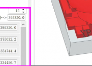
) y6 i1 c0 t8 n! o1 A' e$ f( K. _6.The final segment is a line 20mm long at 90 degreesfrom X+. The entered values can be seen below. The FluteLength value is entered to complete the cutter. This tool can, now, be used in a Planar Profile operation. The PlanarProfile operation should not be confused with a Planar Mill operation with a ProfileCut Pattern. These are twodistinctly different types of operations with different icons. Finally, TrackingPoints would need to be created in the tool for use in the Planar Profile operation./ j8 a; ?- K- s! ~! g" c8 |' a
% Q& T" G4 z) X/ ` M% h( p: N
 8 Y* S* h0 d. p2 R$ ]8 z. X3 a
! i( K* {7 k6 x$ ~6 Q% o5 v4 T9 d d
|
-

|


 |小黑屋|PLM之家-专注工业软件生态建设,大模型CAD创新生态


 发表于 2017-7-2 09:21:46


